 Loading... Please wait...
Categories
Our Newsletter
- Home
- RB Tech
RB Tech
''WHICH RB OIL PUMP DO I USE''
An often asked question quiet easily answered. The pump housings offer some difference between models and the most favorable one is the RB25det or GTR RB26 R32-33. The pic below shows the thickness in the outer rotor outside diameter.

The pic at the top is the RB25 type which is the most favored the pic below is the N1 style.
The question i get asked often is ''how do i tell between N1 and normal RB''
When ordering our billet pump gears youll need to discern between the 2 on order..
The 2 styles of pumps can be discerned by the ammount of screws holding on the backing plate,i am pointing at the extra screw in the N1 type pump- easily spotted.


RB oil pump housings being fitted up with our in house CNC 4150 billet gearsets, and pressure relief valves adjusted for correct pressure, socket head cap screws on backing plates,new oil seal, run and tested on our test bench. sales@lewisengines.com.au
EFFECTIVE RB head porting and flowtesting-----
By far my most favored porting outcome is the GTR RB26 head. Its bigger bowl depth and superior as cast shape is a balltearer once ported correctly. On a full race port job i normally see well over 300cfm from 10mm lift onwards and excellent hi air speed reading as well. The exhaust also showing very hi air speed readings and a 75% exhaust to intake percentage. My DWYER air speed pitot reads in thousandths of feet per second ,the rb26 full port head will rival any s.b chev-ford race heads in air speed. RB full port exhaust air speeds are well into 30% more than any other race head i have tested- non import style.
Flowbench '' inaccuracies''- calibration.
Knowledgable engine builders-porters will use there own flowbench as a back to back testing tool to record their readings and compare improvements and sometimes disprovements. A fool will run from shop to shop with his ported head comparing readings. Most flowbenches read different from bench to bench. I have calibrated my bench to the US edelbrock bench readings. This allows me to comparatively test against the US porters readings.
RB porting outcomes,tuning,power.
Porting outcome is dependant on the customers pocket as to how much can be done as it is charged out per hourly labor rate. The rb25 hydraulic heads, discerned by their short inlet /long exhaust spring, are very popular as an entry level head but are limited in there useage. With a good portjob, our race hi lift springs and 272 custom cams, the combo can provide up to 130rwhp increase at top end and earlier in the power curve dependant on the end camshaft dial in position after proper tuning. The rb25 NEO head shares the same port configure as the GTR RB26 and results after any porting stage are similar to the GTR head. I personally prefer the GTR head for race application for its shim under bucket setup. The neo having a shim over bucket is succeptable to flipping out the shims under valve float situation. A correctly ported RB head of any style will make more power on the engine with any same said boost eg. Recently porting an rb hydraulic head for a tuner/builder after porting flowed 30% more air intake and exhaust. The whole combo was the same as previous except for the ported head, turbo , camtiming, compression all the same. On the dyno a 37rwkw increase was seen from early boost right through . Something exceptional was the way it responded under boost with an earlier fatter power curve. The customers comments where '' it feels a huge increase below boost ,pulls harder through boost ,top end feels similar''. INTERESTING he couldnt feel the top end 'bragging rights figure''................. The more power and torque the engine sees before the maximum top end figure is more crucial. This propels the car faster forwards and in any timed event we know what this means !!!!!
RB power delivery,camshaft event, dynamic compression and valvefloat
Valvefloat is a serious problem which occurs in a turbocharged engine normally when boost is high. The valve spring is pushed open with the boost pushing against the back of the valve as its trying to close. Generally a spring requires the boost pressure added to its seat pressure setup to properly control the valve . In some circumstances intake plenum pressure seen at the valve can be more than the boost guage reads,dependant on blowoff valve setup/type and position. A faster opening ramp rate camshaft will require spring pressure adjustments depending on the rpm needed. As a rule of thumb factory cams with our upgrade springset/dropins will go 9500rpm @23psi boost maximum. When using a 272 profile with this ,same springs and boost, the rpm will need to drop to 8000rpm............. The tell tale signs of valve float are a jagged top end dyno graph or a sharp dropoff in top end curve. The engine on the track shows no signs of valve float until later inspection of parts it is seen. Valve keeper recession in retainer, spring shim fretting, cam lobe unusual hi wear on the nose. Proper choice of parts with our experience will ensure no damage of engine internals. Camshaft dial in position is most important. Its very enjoyable on the dyno to move the cams around and see an earlier fatter dyno curve,,,, normally with some top end reduction,,,,,but this will move the car forward QUICKER. Basically what is happening with cam positioning is the alteration of the engines dynamic compression. For example moving the cams ''in'' or increasing overlap will generally move the power higher and for a longer period of time, reducing the dynamic compression and ''opening up'' the engines breathing . Moving the cams ''out'' or decreasing overlap will generally drop off the top and bring the curve in quicker and fatter towards mid boost, ''closing up'' the engine or restricting its breathing/pumping ability. All turbocharges and camshafts will respond slightly different but this is the general rule of thumb. Think of the engine as a forced air pump and moving cams is the tap controlling its pumping !!!!!.
Darren Lewis.
RB CRANK COLLAR FITTING.


1. Our collars have precision ground internal bores which make it easy to gain the required .002 interference fit to shaft.
Crankshaft must be machined by an engine shop/ crankshaft grinder. Must be ground with a finish similar to a crank journal.
Most crankshaft grinder operators are familiar with the precise measuring to gain the .002 thou interference.
The collar should never be fitted relying on the grub screws to hold it, with the correct .002 thou press on/ interference fit the collar will have sufficient hold to the crank. The grub screws are only to assure it not turning in event of pump lockup etc.
2. Gently warm collar to a light straw color and with a suitable mandrel knock the collar on very smartly.
NOTE, the heat soak from the collar will grab it very quickly so it must be a very fast knock on technique to assure it fitting home easily.
3. Fit grub screws at journal end of collars at 180 deg away from each other, to ensure screws do not hit the crank bolt when doing up bolt.
We want to see our product fitted correctly so EMAIL with any questions.
RB OIL PUMP FAILURES................
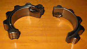
Every second phone call involves a discussion on RB pump failures. It is a dilemma that faces the unaware RB builder but can be addressed in several ways.
Basically the 6 cylinder inline engine is not a balance friendly item to deal with at high rpm. The crankshaft harmonics through the inline 6 crank are inevitable and increase in magnitude as crankshaft stroke increases.
This is no new engineering fact but has to be dealt with and manicured as per each individual combination and customers budget.
The Nissan RB engine will go 'past' or 'through' its harmonic periods very quickly and this will interprate the success or the destruction of most combinations. Some turbocharger combinations will find a huge ammount of rpm per time and these are the 'oil pump killers'. The cranks especially the long stroke RB30 will not be happy in these situations. We find in most race /high rpm engines to stick with a 25 or 26 stroke and when using the RB30 to be limited to max rpm of 7500rpm.
When using an RB30 a constant check of the balancer bolt tension is necessary.The first sign of crank harmonics and too much rpm for a combination, is the loosening of the harmonic balancer bolt in operation. The bolt must be done up to 400nm. This cannot be achieved unless the flywheel or crank is held with appropriate tools. A knocking type hammer or torque wrench and car in gear WILL NOT achieve sufficient tension.
The nissan gear tooth design is very weak and breakage will innherintly happen from tooth root to outer diameter in its thinnest area. The 2 flat internal gear drive flanks are also a weak driving design. Great for a stock engine as nissan designed it for but builders will find the flaws once modifying.
Fixes for these issues are obviously in a race type application a conventional dry sump system. Some budgets and combos that do not allow will require an external wet sump style setup. Alternatively we can supply our moly - billett gears which are successful in all 25 and 26 setups and the RB30 limited to 7500rpm.
This can be very stressful to unaware or ''take the chance'' RB builders but it is inherrant in modifying and developing most engine types. Finding the weak links and modifying them is part of developing any engine model .
For any help or questions please EMAIL --------------- sales@lewisengines.com.au
RB HEAD DRAIN fitting instructions.
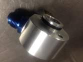
1. Remove rear oil welch plug.
2. Fit alloy billett drain into hole with the #10 fitting facing towards inlet side and two 6mm holes at 9 oclock through 3 oclock.
3. Drill pilot holes thru drain with a 5.8mm drill to locate a centre.
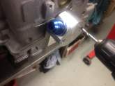
4. Remove drain drill hole 4.7mm and tap 6x1 thread all way through head .
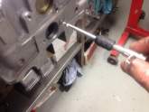
5. Ensure adequate silastic on oring and rear of drain also around 6mm bolt threads. Nissan grey or threebond etc is recommended.
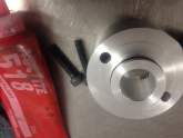
6. FINISH INSTALL . We have designed the drains to be a boltup fit with our RB race sumps. The drain is strong enough to tolerate any gearbox /firewall clashing when removing gearboxes.
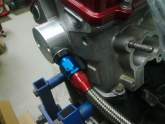
RB oil restrictor fitting instructions.
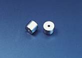
1. Knock down factory restrictor until it bottoms out
2. Deburr hole with appropriate drill bit or countersunk tool
3. Fit supplied restrictor knocking in with punch until restrictor is just below deck. CAUTION use a punch approx 5mm diam so as not to burr over the restrictor hole . The snugger the punch fit to the hole size the better.
4. Gently peen around the restrictor to burr over the deck material to ensure restrictor does not blow towards the head with oil pressure. Check the head gasket to see the shape of the oil feed passage so as not to peen over any surface outside the gaskets region.
NOTE the original factory restrictor must not be removed as it has a check valve ball which doesnt allow oil pressure to drop from head when engine is off. Our restrictors must fit on top of factory restrictor.
email with any questions.....................
RB race pan fitting instructions.

1. Although fitting a sump is relatively easy dont be caught out by not checking oil pickup clearance to bottom of pan. Any race engine build procedure is to check sufficient clearance between pickup to be approx 10 to 15mm and carefully bend pickup to give this clearance .''NEVER ASSUME''
2. When using on an rb30 with h beams make sure rear fins do not hit rods . If so bend fins down accordingly.
3.Fit sump to engine with engine the way up it sits in car. eg offer sump up to block from underneath. This will ensure trap doors do not get hung up on the pickup and ensure their proper operation.
4. Nissan grey engine sealant or Wurth special 250 are sealers of choice and requiring a 5mm high bead in the factory sealant grooves.
RB CRANK BOLT tensioning........
Most often RB harmonic balancer bolts are not tightened correctly.We usually see crank snout damage from a loose balancer after a timing belt change where the mechanic ''thinks'' he has the bolt tight. The rb 25/30 bolt must be tightened to 400nm and the larger rb26 GTR bolt to 460 nm. The only way to tighten to this tension is by locking the flywheel in place with a suitable tool. Failure to do this , especially more so on a race RB30, will entail in balancer movement and in shortime balancer and or crank damage.
''happy times and keep it tight''............................Darren Lewis.
