 Loading... Please wait...
Categories
Our Newsletter
- Home
- Engine Tech
Engine Tech
TD42 Engine modifying tips and problems- discussed..
In the past many years we have built, modified and developed these engines. Hopefully this article will shed some light on the grey areas amongst TD enthusiasts and builders. The problems we hear about email after email and phone call from all over Australia, mainly involves the turbo charging of a non turbo engine,and thereafter the problems they created themselves.
The factrory turbo Td42 engines at factory boost level has its owns inherrant problems. Once modified beyond these boost levels problems can occur and as boost levels are more the issues are greater. My favorite and tried boost level which is a happy day is around 15 psi. I do not consider these engines to be engineeringly design capable of surviving under higher boost levels. Sure some guys get lucky at 30psi but under heavy load towing conditions that engine could be seeing near 30 psi for the extent of a trip just to maintain 100kmp/h !!!.
The danger is the coolant temperature climb under high load ---long time pulling. It is not unusual to see the coolant temp increase 1 degree per second in these conditions. This is where the problems occur. In an ideal tune situation with EGT temps at a good safe temp and fuel supply etc ideal, the coolant temp will still climb dramatically. And you can only imagine what can happen when EGT and mixture -burn etc is not ideal ??? An engine with serious permanent destruction.
When mixtures arent ideal the piston crown temp will increase to a point where pistons will sieze across the gudgeon pin axis. This siezing is caused through the severe crown heat and also the thin walls in between each bore that will flex and distort. Most often when reconditioning and pulling sleeves we will see lateral cracking in the parent bores halfway up the sleeve hole. These blocks are then throw away.
A more common problem we have seen is the pre combustion chambers moving which allows the gasket to not seal and therefore overheating occurs from there. The design of the engine with the compression sealing fire ring going across the precomp chamber is a bad design and limits the power -boost and mods these engines can longetivitively handle. The pre comp chambers moving is solely caused from overfueling or incorrect fuel timing-quality. A large volume of fuel in the Diesel engine creates excess chamber or piston crown temperature,,,unlike and opposite to a petrol engine. Black smoking in a diesel is a'' lean'' condition meaning the engine has minimal fuel as it is being thrown out the exhaust and piston crown temp will keep climbing because there is insufficient fuel in the chamber to burn therefore ''lean''.
I hear quiet often of guys using 12mm or 13mm injector pumps these pumps increase the fuel supply to the engine and could increase the crown heat problem. It would be ideal to see the fuel injection timing points changed to an optimum delivery point.... Ive not seen injector pump builders do this yet. The mechanical injector pump once again has its limitations.
Not to scare off the TD enthusiast but to try to offer some insight on the fact that you will damage the engine when modifying if not qualified or have minimal knowledge. Even so when asking too much from them you can create problems as well.
Crankshaft breakage is another issue that is thrown around. Basically the 6 cylinder engine is a crankshaft harmonic problem sponge... The factory crank is plenty strong in design and i normally see issues of crank breakage after a rebuild. Possible causes for this are lack of cracktesting pre build. The engine has probably been through a piston meltdown and cracked the crank in the fillett radius, an unaware builder lacks to cracktest it.. Some breakages ive also seen from guys revving them way beyond the items ability. The more boost and larger turbo and power generated will cause the engine to rpm very quick and this will go through its harmonic periods very fast and make the crank flex and crack-breakage. I do feel a lightweight flywheel and harmonic balancer will help if this situation cannot be avoided.
All in all keep it under 15psi and youre TD in perfect tune will last 500,000km.
Darren Lewis.
TD42 Nissan sleeve fitting issues.
When fitting liners to these engines it is imperative to measure the parent bore that the sleeve is fitted into. If the internal bore,after the sleeve is removed, is out of round it will have to be straightened up and a custom OD sleeve made. We can provide this for our customers. A lot of shops will fit the new liners and after some use often within weeks the liners will move and the top sleeve surface will drop below the deck face not allowing the gasket to seal properly and engine stripdown is inherrant to rectify.
I will only sell semi finished sleeves in my rebuild kits as it is not successful to fit a finished liner in these engines as the bore will be out of shape once fitted. The semi-finished sleeve leaves you .25mm material internally to bore to get it nice and round etc. It is always advisable to cracktest the block after old sleeve removal as i have seen cracks in the parent material which if a new sleeve is fitted over it will cause movement.
I prefer to sit the sleeve top flange above the deck 3 thou for a super gasket retention.
.........................................................................................................................................................................
Navara D40 D22 engine fixes.
After alot of R&D i can now provide YD25 owners with a bulletproof engine and or parts supply. Now stock early steel crankshafts modified and balanced to stop crank cracking issues. I have noticed after a series of cycles approx 90,000km to 160,000km the YD crankshaft will crack at the no.4 rod journal. This is a combination of poor metal, balancing issues and strength. The YD cranks are a cast material not providing sufficient strength.
Replacement of the dual mass factory flywheel to a solid flywheel will enhance this problem. It is evident looking at the oil pump drive gear that alot of crank harmonics takes place in these engines. I know have a solution using balance shaft removal and proper crank balance techniques.
I have also found the solution for bent valves etc . Youve probably heard issues of an engine on startup just stopped shortly after cranking and on stripdown had smashed cams,valves etc ? This being a result of a stretched timing chain allowing the tensioner to move back far enough and chain skips teeth--valves into piston collision. On startup sometimes if the engine doesnt start straightup on cranking it will stall and kick backwards- allowing tensioner piston to travel backwards and giving chain enough slack to skip over the gearteeth causing timing to go out of phase. Lewis Engines now provided dual row upper and lower chainkits with modified tensioners to prevent this..
I also have a full range of ARP studs to correctly hold these engines together. The factory fasteners are not reusable and Nissan dealers are not stocking them readilly. I have ARP studkits for conrods,mains and headstuds. We are currently designing a 10mm thick steel girdle to help retain the main caps and tie the cap area up nicely---available soon.
Lewis Engines can now provide a properly modified steel crank,balance shaft removal and rebalance to prevent this issue. Alot of other issues ive found with the engine manufacture is
1. Insufficient main and rod bearing crush
2. Excess vertical oil clearance
3. Oil pump and harmonic balancer drive flat contact wear
4. Insufficient timing chain strength and tensioner piston backtravel issues.
5. Nissan factory recommended 5/30 weight oil ??? rediculous quality for this type engine......
All of these problems we can address for you in a full build-repair,parts supply and or machining.
To keep youre YD25 reliable and enjoyable. Active for all Patrol -Navara D40 and D22 early to present.
.............................................................................................................................................................................
HARLEY DAVIDSON DYNAMIC CRANKSHAFT BALANCING.
Recently finding the need to accurately balance the v-twin crankshafts we have gone through a lot of developement and setup to provide this to our bike customers.
Its not cheap as the flywheel halves have to be setup and trued twice so time consuming job.
This will only be suitable for early engines shovel and all evolution models.
We can tailor youre style of riding to how smooth the engine will be at a particular road speed.
for eg. with a balance factor of 50% the engine will be smooth at lower rpm and rough at hi speeds, with the factor at 58% this will allow the engine to go through its harmonic period in low rpm and be smooth a silk around 90 to 120 kmph.
Common rail diesel fuel filtration.
Diesel acts as a lubricant and moves around the fuel injection system freely, until it is placed under ultra-high pressure and burnt in a gas like state to drive the vehicle. This makes the fuel injection system very susceptible to particle contamination and more importantly water damage.
Are you able to remember back to the days before ULSD (Ultra Low Sulphr Diesel) and LSD (Low Sulphur Diesel)? Do you remember having to drain the water out of your 4×4 fuel filters? Most of us do. But we haven’t had to do it for a long time have we? The answer to this is the change in the fuel itself. Ultra Low Sulphur Diesel that we have today, suspends water in the fuel. This is called emulsified fuel. This means you cant see it in normal circulation like “whole water” which is separate in the bottom of the fuel bowl.
As the Australian and New Zealand climate fluctuates between hot and cold weather conditions, water condensation starts to develop. The water molecules from this condensation enter the fuel system and mixes with diesel to reduce the overall lubricity of diesel within the fuel system. This causes friction damage with internal components and as metal particles start to break off and move around the fuel system, this is where damage starts to compound and impact other parts and components within the fuel system.
Most diesel vehicles are fitted with a 2-5 micron final filter (size of bacteria) installed by the O.E.M to remove the finer contamination. An efficient filter should be fitted- 30 micron filter (size of lint) which is specifically selected to remove the majority of dirt, rocks, dust, rust, scale, yeasts, mould, bacteria, algae, acid and most importantly water that may be present in the fuel before it enters the engine.
These filters can be purchased from us to combat the inherrant engine problems which can occur in late model common rail diesels usually from 06 -on.
The factory fitted filters are simply not efficient enough. It is common for a set of late model common rail injectors to fail within 70,000km if not attended to with a healthy repair bill. Not to mention the internal possible damage to the engine when failure occurs-eg lean mixture or overfueling /hydraulic lockup.
Quench and Chamber design in RB engines
Its important not in only the Nissan RB engine but in all engines to have a combustion chamber shape that enhances the cylinder burn and tumble characteristics. The RB has two opposed quench pads to correlate with the pented piston crown design. These pads will push the mixture into the centre of the cylinder on piston upstroke. It is most important to generate the burn centrally in the chamber to push the piston down smoothly as not to overload engine parts.
The picture below is one ive recently seen on how NOT to modify an RB combustion chamber. This has obviously been done by an inexperienced head porter with minimal knowledge on the turbocharged combustion chamber importance. The chamber has had the quench pads removed and the chamber rounded off ,which inherrantly causes a bad burning chamber resulting in incomplete combustion.
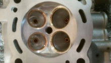
In early developement of a few SR20 GTIR engines, these have a rounded chamber as this person has modified the RB chamber. The GTIR engines responded horribly to ignition timing and where very difficult to make horsepower. An RB chamber modified in this manner will produce the same dramatic results.
Lesson learnt people ''leave the quench pads '' on RB chambers and just run a nice 1mm chamfer to stop heatspots. There is no reason to modify what Nissan designers spent millions of dollars on developing...... Happy head porting. Darren Lewis.
SURFACE FINISH and machining tips block deck and head .
Surface finish on block deck surfaces and cylinder heads are even more important now with the regular use and popularity of the Multi layer steel head gaskets.
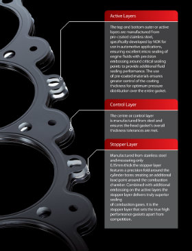
Commonly referred to as the MLSR. The MLSR gasket is basically diesel engine technology which has carried through to the automotive use and favoring turbocharged and hi output modern engines. The old style composite gasket would have a certain ammount of give and fill any irregularities in the surfaces. The MLSR requires a finish of less than 20ra.
Without a stylus to measure the surface finish- the best way to explain is it needs to be smooth to feel with the fingernail, not shiny smooth ,but needs some grain. Ideally a milled surface finish using a correctly sharpened tungsten tip will work.
The MLSR gaskets have a .001 thou coating of Viton to aid in sealing,this is the black coating youll see on the surfaces.
The multi layers and raised sealing beads are designed to interlock together when squeezed and provide an ultimate seal. Often referred to by japanese manufacturers as ''stopper'' gaskets.
An often seen no-no is the use of scotchbrite wheel to remove and clean the surface. I get guys bringing blocks to me that have been messed with in this way and believe me once on my machine after the first cut its very evident that alot of material has been removed by their 'gasket removing' tools. The only way to treat a deck or head face is machine it .
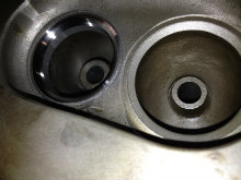
Below youll see after the first cut how bad the block surface is attacked by such devices.
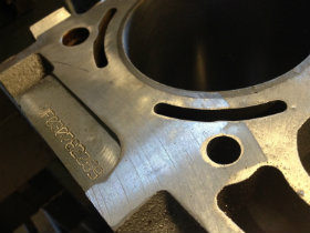
Gasket thickness choice is governed by the piston to deck height ,usually requiring .030thou piston to head clearance. Care must be taken when measuring up as some short skirt pistons will rock alot .The trick is to sit the piston in the bore squarely measuring from side to side and use that deck measurement as youre referal to chosen gasket thickness.
Darren Lewis.
VALVE SPRING-BOOST ISSUES.
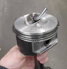
A few recent discussions with some builders regarding valve spring bounce or ''float'' in turbo applications has led me to explain the importance of addressing these issues.
Obviously valve float can cause catastrofic damage to engine parts and heres a few tips on how to help combat it.
When hi ramp rate cam profiles are used it becomes important to follow up the valvetrain upgrade to stop spring bounce. The spring needs to follow the cam lobe to ensure the valve closes effectively each event to aid in correct performance. Also in turbocharged application we have boost pressure trying to push the valve off its seat whilst closed and oppose its closing effectiveness.
A rule of thumb is that if 20 pounds boost is used then 20 psi must be added to the closed pressure of the valve spring. This is a rough rule of thumb but in some occurances pressure at the actual back of the valve can be more than manifold measured boost pressure.
It is quiet a developement process to stop valvefloat when boost pressures exceed 24 psi.
An example recently also was a customer approached me with a set of heavy duty springs normally capable of 20 psi boost that he stated where valve floating.After some discussion i realised he was using factory nissan camshafts. The maximum lift being approx .380 lift. The spring would therefore only have 120 psi open tension, this with the 20 psi boost was actually valvefloating because the spring didnt therefore have sufficient open tension.
The seat tension is one thing but the open tension is equally important. If for example he had fitted my custom 272 cams it would have lifted the valve at full open lift another .150 thou enabling the spring to have 200 psi open tension - stopping valve float !!!
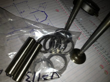
It is important to therefore match the cam lobe profile to spring tension required for an ammount of boost. Some odd occasions because of extra boost at the valve than thought, which is immeasurable, can require more seat and open pressure than calculated. This being part of the joys in developing a race engine which holds together. Hopefully this article has helped and a quick email anytime is always welcome.
Darren Lewis.
JOWETT 4CYLINDER ''BOXER'' engine rebuild.

The Jowett 4 cylinder engine was produced in Britain from 1930,s thru to the 50,s and has quiet a common interest amongst restorers. Its alloy block and wet sleeves was quiet advanced for its time and shares the same ''boxer'' type opposed 4 cylinder design as Subaru uses to this day.
I currently have a half dozen of these engine in rebuild process for enthusiasts from over the southern hemisphere. Its cast iron cylinder head makes it a very durable engine.
Through the builds i have found it necessary to enhance the engines with some upgrades and ''modern technology''. We have used an 'oval' style LAYSTALL crankshaft which has larger counterweighting and made from very nice heat treated steel. Even though the engines produce not much in excess of 40 horsepower there standard cranks often crack. The oval crank once balanced nicely will be superb in its operation. Other process used to strengthen the crank are the regrinding of the fillett radii to produce a 1/8 th radius and then taping up the journal surface and shotpeening the radii with 280 fine steel shot. A process used on race crankshafts but will inherrantly give this engine a lifetime of strength.
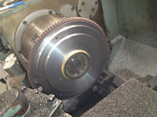
The pic below shows the crank radii exposed ready for shotpeening and crankshaft balancing process.
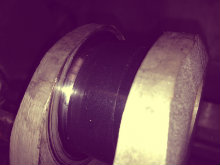
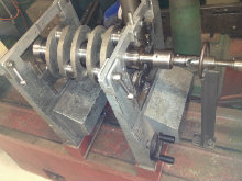
Accurate balancing of the crank assembly and lightened flywheel ensures the engine will rotate smoothly. The bearings shells are all individually labelled and torqued into the cases and conrods . The crankshaft is reground with careful measuring of each individual bearing journal to give .002 thou vertical oil clearance. Another process used in race engine building.
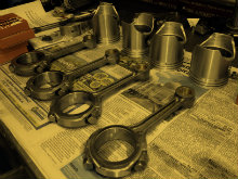
Piston and rods have been cracktested, resized to suit the Perkins bearings and glassbeaded along with fitment of new bushes. The JP pistons are a very good product and balance and size up nicely to the 73.5mm bores.
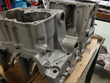
Alloy engine cases are first hotwashed and then glassbeaded to inspect and cracktest. Most of the head studs on removal will break off in the case from being corroded in. This is no concern as i am helicoiling all head stud holes using 3/8 BSF recoils and manfacturing new head stud sets from hi grade steel. I make the helicoils and studs 10mm longer in the block so as to give added strength on the stud clamping ability.
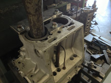
The barrels are clamped in situ in the case and bored straight to the deck then honed on our Sunnen hone.
One thing i have noticed with these engines is the quality of the alloy for their period. From restoring alot of british engines, it is very noticeable that these engines have quality of material and lack off corrosion for their age.
Cases are machined to suit Perkins diesel shells and Toyota thrust washers. The washers are located in the rear main journal . Camshaft is reground using an early Kent 1600 Ford profile which has approx 10 degrees more duration than the original factory Jowett profile and should help ''liven up '' the torque output. Cam followers are convex ground in house. The bottom end is assembled with meticulous hours of cleaning. The bottom end being assembled................................
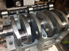 ,,,,,now time for the heads !!!!!
Cylinder heads are hot washed and inspected then glassbeaded and cracktested.
Fitting of premier valve guides and hardened exhaust inserts will maintain the life of the seats with the engine running on our modern ULP fuel.
